
Log and Antilog amplifiers.
Introduction
The electronic circuits which can perform the mathematical operations such as logarithm and anti-logarithm with an amplification are called as Logarithmic and Anti-Logarithmic amplifiers respectively. The applications for log/anti-log amplifiers include signal compression and process control.
1) Log Amplifier
A logarithmic amplifier is an electronic circuit that produces an output that is proportional to the logarithm of the applied input. An op-amp based logarithmic amplifier produces a voltage at the output, which is proportional to the logarithm of the voltage applied to the resistor connected to its inverting terminal. The circuit diagram of op-amp based logarithmic amplifier is shown in figure 1.
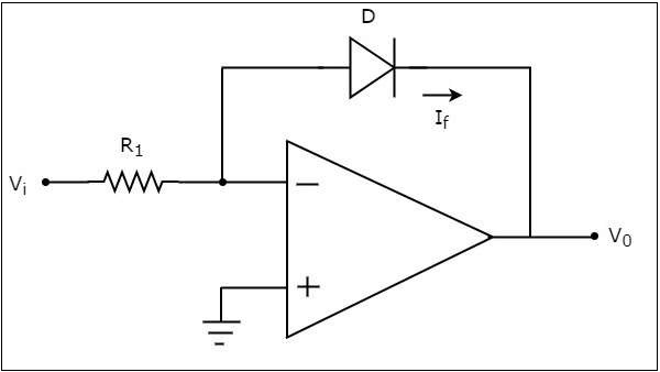
In the above circuit, the non-inverting input terminal of the op-amp is connected to ground. That means zero volts is applied at the non-inverting input terminal of the op-amp.
The nodal equation at the inverting input is as follows
from the equation 1,the feedback current is
When the diode is forward biased, the current flowing through the diode is
Where,
Is is the saturation current of the diode,
Vf is the voltage drop across diode, when it is in forward bias,
VT is the diode's thermal equivalent voltage.
The KVL equation around the feedback loop of the op amp will be
Substituting the value of Vf in Equation 2, we get
Applying natural logarithm on the both sides
In the above equation, the parameters n, VT and Is are constants. So, the output voltage V0 will be proportional to the natural logarithm of the input voltage Vi for a fixed value of resistance R1.
The output voltage V0 has a negative sign, which indicates that there exists a 180° phase difference between the input and the output.
2) Antilog Amplifier
An op-amp based anti-logarithmic amplifier produces a voltage at the output, which is proportional to the anti-logarithm of the voltage that is applied to the diode connected to its inverting input. The circuit diagram of an op-amp based anti-logarithmic amplifier is shown in figure 2.
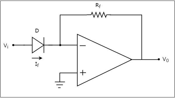
In the circuit shown above, the non-inverting input of the op-amp is connected to ground. According to the virtual ground concept, the voltage at the inverting input of op-amp will be equal to the voltage present at its non-inverting input. So, the voltage at its inverting input will be zero volts.
The nodal equation at the inverting input node is
When the diode is forward biased, the current flowing through the diode is given by
Substituting the value of If in Equation 4, then
The KVL equation at the inverting input of the op-amp will be
So,
Substituting the value of Vf in equation 5, then
In the above equation the parameters n, VT and Is are constants. So, the output voltage V0 will be proportional to the anti-natural logarithm of the input voltage Vi, for a fixed value of feedback resistance Rf.
The output voltage V0 has a negative sign, which indicates that there exists a 180° phase difference between the input and the output.