
Wien bridge oscillator using operational amplifier.
Introduction
Wein Bridge Oscillator is an electronic device that generates sine waves. In the year 1891, Max Wein developed a bridge circuit to measure the impedances. William R.Hewlett designed the Wein-Bridge Oscillator using the Wein bridge circuit and the differential amplifier. Here the Wein bridge is connected in a positive feedback loop between the amplifier output and differential inputs. This can also be viewed as a band-pass filter that provides positive feedback connected to a positive gain amplifier. The bridge circuit is composed of four resistors and two capacitors. The bridge is balanced at the oscillating frequency and has a very low transfer ratio.
Circuit Diagram of Wein Bridge Oscillator
Wein Bridge Oscillator is a two-staged RC coupled amplifier circuit. It has a feedback loop with a series R1C1 circuit, also known as a High-pass Filter circuit, connected to a parallel R2C2 circuit, also known as a Low-pass Filter circuit. This connection forms a selective second-order frequency-dependent Band-pass filter. This filter has a high Q- factor at a selected frequency.
The component values of both the RC circuits are the same. At the resonant frequency, the phase shift of the signal will be 0 and the circuit will have good stability and low distortions. Besides RC circuits the other two arms of the Weinbridge consist of two more resistors R3, R4. Below is the circuit diagram of a Wein bridge oscillator using OP-Amp.
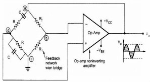
When higher frequencies are applied, the reactance of the capacitors connected in the Wein-bridge is very low. This short circuits the resistor R2 and its output voltage will be zero. At lower frequencies, the higher reactance of the capacitors is observed, and capacitor C1 acts as an open circuit thereby causing the output voltage to be zero. This feature of Wein-bridge observed at the application of lower and higher frequencies, makes it a lead-lag circuit. Here Op-Amp is used as the non-inverting amplifier. The output voltage from the Wein-bridge is fed back to both inverting and non-inverting terminals of the Op-amp.
Operation of Wein Bridge Oscillator using IC741
In a Wein bridge oscillator, when lower to higher frequencies are applied, at a particular frequency, the value of resistance and capacitor reactance becomes equal to each other. At this point, the maximum output voltage is observed. This frequency where maximum voltage is derived is known as the “Resonance Frequency” of the Wein bridge oscillator and is denoted as fr.
The formula for the calculation of resonant frequency is as follows
At the resonant frequency, the phase shift between input and output will be zero. The magnitude of the output voltage will be one-third of the input voltage.
The output of the op-amp is given as input to the bridge circuit from points a and c. The output from the bridge is derived from points b and d and given as input to the op-amp. A portion of the amplifier output is feedback to the positive or non-inverting terminal of the op-amp through the voltage divider circuit, formed by the series combination of resistor and capacitor. Another portion of the output is feedback to the negative or inverting terminal of the op-amp, through the impedance of 2R magnitude.
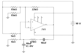
Here, the feedback network provides zero phase shift. Since the amplifier is non-inverting it also has zero phase shift. Hence, the combination of feedback bridge and non-inverting amplifier produces zero phase shift around the loop. Thus, the required condition for the generation of oscillations is achieved. The circuit of the Wein bridge oscillator using IC741 is given below.
Advantages of Wein bridge oscillator
- The overall gain of the oscillator is high as it uses a two-stage amplifier.
- As no inductors are used in the circuit, there is no issue of interference from external magnetic fields.
- This oscillator produces a stable sinewave without any distortions.
- The frequency of the oscillations can be changed by changing the values of capacitors or by the use of a variable resistor in the circuit.
- The Wein-bridge oscillator has good frequency stability.
Disadvantages of Wein bridge oscillator
- The two-stage amplifier type of oscillator requires more devices for construction.
- This oscillator cannot generate very high frequencies, because of the limitations placed on the amplitude and phase-shift values of the amplifier.
Applications:
- These are highly used for audio testing.
- Clock signals for testing filter circuits can be generated by this oscillator.
- Used in distortion testing of power amplifiers.
- These are also used as excitation for the AC bridges.